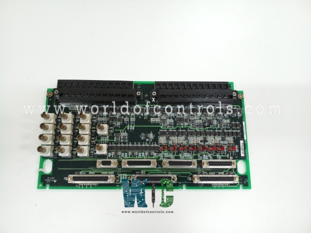
SPECIFICATIONS
Part No.: IS200TVIBH2B
Manufacturer: General Electric
Country of Manufacture: United States of America (USA)
Size: 13 in. x 7 in.
Temperature rating: 0 to 60 oC
Number of Channels: 13
Product Type: Vibration Terminal Board
Availability: In Stock
Series: Mark VI
Functional Description
IS200TVIBH2B is a vibration terminal board developed by GE. It is a part of Mark VI control system. The TVIB system is compatible with Bently Nevada's Proximitor, Seismic, Accelerometer, and Velomitor probes. These vibration probes receive power from the VVIB boards, operating in either Simplex or TMR (Triple Modular Redundancy) mode. After the probes capture signals, they transmit these signals back to the VVIB boards. Here, the analog-to-digital conversion process takes place, transforming the signals before sending them over the VME bus to the central controller.
Shaft Vibration Monitoring in Mark VI System
- The Mark VI system employs Bently Nevada probes for meticulous shaft vibration monitoring, ensuring precision and reliability in assessing machinery health. A maximum of 14 probes can be directly linked to the TVIB terminal board, where two of these probes can be connected via cabling to the VVIB board.
- These probes play a pivotal role in capturing vibration data crucial for comprehensive monitoring and analysis of machinery dynamics within the system.
Signal Processing and Transmission
- Upon connection to the terminal board, the signals from these probes undergo processing via the VVIB board.
- The VVIB board digitizes displacement and velocity signals, facilitating the transmission of this digitized data over the VME bus to the central controller.
- This transmission mechanism ensures that crucial vibration data reaches the controller for further analysis and decision-making processes.
Compatible Vibration Probe Types
The TVIB terminal board is compatible with various types of vibration probes, enabling versatile monitoring capabilities. The available probe types include:
- Proximity
- Velocity
- Acceleration
- Seismic
- Phase
Features
- H2A variant distinguishes itself by incorporating BNC connectors, allowing portable vibration data gathering equipment to be seamlessly plugged in.
- This functionality is particularly useful for predictive maintenance purposes, enabling swift data retrieval for proactive machinery health assessments. Both board types are equipped with connectors designed for permanent cabling to Bently Nevada vibration monitoring equipment.
- This setup facilitates continuous and reliable measurement and analysis of turbine vibration, aiding in ongoing monitoring and analysis of machinery health.
- Within the system, the controller manages the generation of alarms and trip logic related to vibration, eccentricity, and axial position. This centralized control mechanism allows the controller to process incoming data, detect anomalies, and trigger appropriate actions or alarms based on preset parameters for maintaining system integrity and safety.
Installation
During the installation process, fourteen vibration probes are meticulously wired to the two terminal blocks, with each probe requiring three wires for proper connectivity. These probes, crucial for comprehensive vibration monitoring, are integrated into the system to capture essential data regarding machinery dynamics.
- Probe Configuration via Jumpers:The system allows for the configuration of the first eight probes using jumpers JP1 through JP8. These jumpers serve as selectors, enabling the system to identify and categorize the type of each probe. This configuration step ensures accurate signal processing and interpretation based on the specific characteristics and functionalities of individual probes.
- Optional Connectors for Bently Nevada System:The installation procedure incorporates optional connectors, namely JA1, JB1, JC1, and JD1, specifically designed for Bently Nevada systems. These connectors offer flexibility in the system setup, providing an alternative or supplementary connection method tailored for Bently Nevada equipment integration. Their use remains optional, allowing adaptability based on the specific requirements or preferences of the installation process.
- Wiring Details for Optimal Functionality:The wiring process, encompassing three wires per probe, ensures proper and stable connectivity between the vibration probes and the terminal blocks. Each wire serves a crucial function in facilitating the transmission of data essential for the comprehensive monitoring and analysis of machinery vibration.
- System Adaptability and Customization:The configuration options through jumpers and the inclusion of optional connectors highlight the system's adaptability and customization capabilities. These features allow for tailored integration of vibration probes, ensuring optimal functionality and compatibility with the specific needs and equipment preferences, particularly within Bently Nevada systems, if chosen to be incorporated.
The WOC team is always available to help you with your Mark VI requirements. For more information, please contact WOC.
Frequently Asked Questions
What is IS200TVIBH2B?
It is a vibration terminal board developed by GE under the Mark VI series.
What conditions trigger probe faults, alarms, or trips?
Any instance where an X or Y probe pair exceeds its defined limits initiates probe faults, alarms, or trip conditions. This occurrence prompts system responses, indicating potential issues with probe measurements.
How are position inputs for thrust wear, differential expansion, and eccentricity monitored, and what causes faults?
Similar to vibration inputs, position inputs for various measurements are monitored, using only the DC component for indication. If these positional inputs surpass predefined maximum limits, the system generates faults, indicating deviations from expected operational parameters.
Why are these diagnostics and limits essential for system operation?
These diagnostics and limits are vital for continuous system health monitoring and protection. They ensure probe and position inputs remain within safe ranges, facilitating early detection of potential issues and enabling timely interventions for maintaining equipment integrity and safety.
