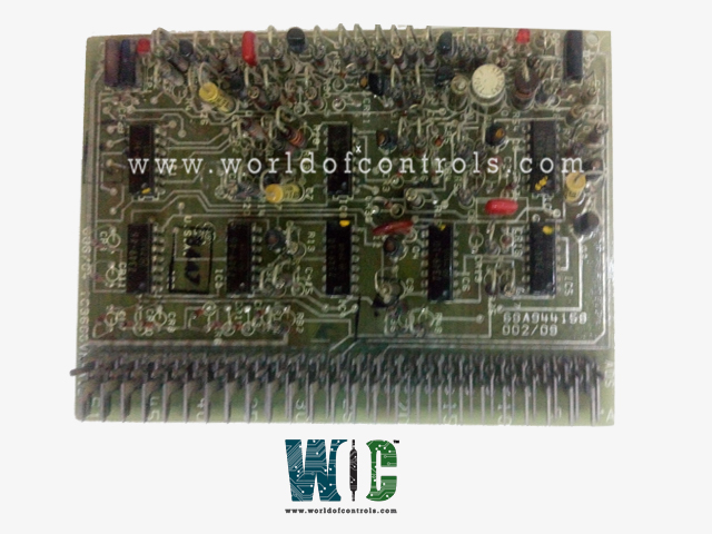
IC3600VMPA1 - Mechanical Protective Board

IC3600VMPA1 - Mechanical Protective Board IC3600VMPA1 - Mechanical Protective Board

World Of Controls understands the criticality of your requirement and works towards reducing the lead time as much as possible.

IC3600VMPA1 - Mechanical Protective Board is available in stock which ships the same day.

IC3600VMPA1 - Mechanical Protective Board comes in UNUSED as well as REBUILT condition.

To avail our best deals for IC3600VMPA1 - Mechanical Protective Board, contact us and we will get back to you within 24 hours.

SPECIFICATIONS

Part No: IC3600VMPA1
Manufacturer: General Electric
Function: Mechanical Protective Board
Series: Mark I and II
Repair: 3-7 Day
Availability: In Stock
Country of Manufacturer: United States (USA)

Functional Description

IC3600VMPA1 is a Mechanical Protective Board developed by GE. It is a part of Mark I and II control system. The core of the protection system lies in the VMPA card is responsible for ensuring the safe operation of the system. The card performs several essential functions, primarily revolving around generating key signals and biases:

  • Generation of the "4" Signal: The VMPA card generates the "4" signal, which plays a pivotal role in the protection system. This signal is used for critical control functions and serves as a safeguard against potentially harmful operating conditions.
  • Shutdown Bias to Servovalves: In addition to the "4" signal, the VMPA card provides a shutdown bias to the servovalves. This bias helps in swiftly shutting down the system when required, ensuring the safety of the equipment and the environment.

Primary Outputs

The VMPA card produces three primary outputs that are integral to its operation:

  • Start Check Signal: The Start Check Signal, found on PIN OSTCK, is a logic "0" that acts as a prerequisite for initiating the turbine.
  • Servo Trip Signal: The Servo Trip Signal, located on PIN SRT, is responsible for supplying a shutdown bias to the fuel servovalves, facilitating a controlled shutdown of the system when necessary.
  • The "4" Signal: The "4" Signal, available on PINS 4RD, 4, and 4!, serves as a permissive signal for system operation. It is a key indicator of safe conditions. Any conditions that may pose a risk to the turbine trigger the VMPA card to drop the "4" circuit, thereby preventing further operation.

Start Check Circuit

The Start Check Circuit is crucial for initiating the turbine and ensuring its safety. It involves the "SUM 1" gate in the top left corner.

  • "SUM 1" Gate Logic: The "SUM 1" gate checks if all its inputs are "1." If they are, it produces an output of logic "0," which is the prerequisite for starting the turbine. Any logic "0" input to the "SUM 1" gate inhibits the starting process.
  • Setting the Flip-Flop: To set the flip-flop in the top center of the symbol, the Start Check Signal must be "0." Several conditions must be met for this, including PIN m being "0," PIN 63QT being "0" (tied to DCOM), and the trip bus being a logic "1."
  • Resetting the Flip-Flop: The flip-flop can be reset if the trip bus goes to a logic "0," leading to the "4" circuit dropping out. There are multiple pathways to introduce a logic "0" on the trip bus.

Paths to Trip Bus Manipulation

Several paths can introduce a logic "0" to the trip bus, leading to the reset of the flip-flop:

  • Emergency Stop Signal: The first path starts at PIN ESTOP, which carries the emergency stop signal. This pin is connected to P28 through normally closed relay contacts. Opening these contacts will cause the flip-flop to reset.
  • Majority Logic Gate: Another pathway is through the majority logic gate. A logic "0" on any two inputs of this gate will result in a logic "1" output, maintaining the trip bus as "1."

Utility Application

  • In utility applications, external circuitry is often added to make the majority logic gate function as a negative "AND" gate, ensuring that two logic "1" inputs are required to trigger a logic "0" output, thus keeping the trip bus at "1."

WOC is happy to assist you with any of your GE requirements. Please contact us by phone or email for pricing and availability on any parts and repairs.

FREQUENTLY ASKED QUESTIONS

What is IC3600VMPA1?
It is a Mechanical Protective Board developed by GE

How does the Start Check Signal relate to turbine operation?
The Start Check Signal, a logic 0 on PIN OSTCK, is a prerequisite for initiating the turbine. If this signal is not in the correct state, the turbine will not start.

What is the role of the Servo Trip Signal generated by the VMPA card?
The Servo Trip Signal, available on PIN SRT, provides a shutdown bias to the fuel servovalves, ensuring a controlled shutdown of the system when required.

What is the SUM 1 gate, and why is it important in the protection system?
The SUM 1 gate is a logic gate that checks if all its inputs are 1. It produces a logic 0 output, which is a prerequisite for starting the turbine. Any logic 0 input to this gate inhibits the starting process.