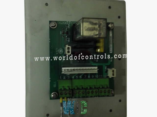
World Of Controls understands the criticality of your requirement and works towards reducing the lead time as much as possible.
DS200CPCAG1A - Contactor Pilot Board is available in stock which ships the same day.
DS200CPCAG1A - Contactor Pilot Board comes in UNUSED as well as REBUILT condition.
To avail our best deals for DS200CPCAG1A - Contactor Pilot Board, contact us and we will get back to you within 24 hours.
SPECIFICATIONS:
Part No: DS200CPCAG1A
Manufacturer: General Electric
Function: Contactor Pilot Board
Series: EX2000
Operating temperature: -35 to 65 ºC
Power Supply Voltage: 25 V dc
Board Size: 23.8 cm high x 8.6 cm
Weight: 0.45 kg
Availability: In Stock
Country of Origin: USA
FUNCTIONAL DESCRIPTION:
DS200CPCAG1A is a Contactor Pilot Board manufactured and designed by General Electric as part of the EX2000 Series used in the GE Excitation Control System. To control the opening and shutting of a contactor, the CDBA board supplies the electricity. 115 v is the coil voltage for the contactors used with the CPCA. The CPCA transforms incoming 115 V ac into 105 V dc to drive the contactor coil. When a contractor needs to be closed and kept closed, the CPCA card, as opposed to the CDBA board, provides the entire voltage.
TEST POINTS:
CPH - CPCA power positive input test point. All test measurements must be made with isolated test equipment that is capable of measuring floating potentials since CPH is not referenced to the drive's common level.
CPN - CPCA power negative input test point.
PSP - PSP Testpoint for Positive Input to CPCA Coil.
PSN - For CPCA coil control negative input, there is a PSN Testpoint.
BOARD ADJUSTABLE HARDWARE:
JP1:
JP2:
RV1:
FEATURES:
WOC has the largest stock of GE Excitation Turbine Control System Replacement Parts. We can also repair your faulty boards and supply unused and rebuilt boards backed up with a warranty. Our team of experts is available round the clock to support your OEM needs. Our team of experts at WOC is happy to assist you with any of your automation requirements. For pricing and availability on any parts and repairs, kindly get in touch with our team by phone or email.
FREQUENTLY ASKED QUESTIONS:
How to Check Price and Availability For Contactor Pilot Board?
Please Contact World of Controls FZE for sales at +1 609 385 1231 or Request a Quote.
What Payment Options do You Accept?
Bank Transfer is the preferred payment method. For more payment options contact us.
How are boards packaged for shipment from WOC?
Parts are placed in antistatic packets and securely packed in ESD boxes cushioned with ESD Foam designed to safeguard electrical components.
WORLD OF CONTROLS warrants that from the date of delivery for a period of 36 months all UNUSED / REBUILT goods shall conform in all material respects with their description and any applicable specification.
WORLD OF CONTROLS warrants that from the point of delivery all Repairs will accord with their description and/or remain functional subject to the performance of the Repair Item for a period of 24 months.