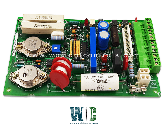
World Of Controls understands the criticality of your requirement and works towards reducing the lead time as much as possible.
DS200CDBAG1B - Contactor Driver Board is available in stock which ships the same day.
DS200CDBAG1B - Contactor Driver Board comes in UNUSED as well as REBUILT condition.
To avail our best deals for DS200CDBAG1B - Contactor Driver Board, contact us and we will get back to you within 24 hours.
SPECIFICATIONS:
Part Number: DS200CDBAG1B
Manufacturer: General Electric
Series: Mark V
Product Function: Contactor Driver Board
Power Requirements: +5 V dc, 6 A
Number of relay channels: 12
Trip Solenoid Rating: 125 V dc
Power supply voltage: 28 V dc
Voltage Range: 18 - 32 VDC
Mounting Option: DIN-rail mounting
Operating temperature: -30 to +65 degrees Celsius
Size: 15.9 cm high x 17.8 cm width
Repair: 3-7 Day
Availability: In Stock
Country of Manufacturer: United States (USA)
Manual: GEH-6005
FUNCTIONAL DESCRIPTION:
DS200CDBAG1B is a Contactor Driver Board manufactured and designed by General Electric as part of the Mark V Series used in GE Speedtronic Control Systems. The DS200CDBA Contactor Driver Board (CDBA) provides power to open and close a contactor under the control of the DS200DCFB Power Supply Board (DCFB) or DS200SDCI Do Power Supply and Instrumentation Board (SDCI). Contactors used with the CDBA have coil voltages of 30 to 40 V. To close a contactor, the CDBA applies 105 V de for 250 msec to force the contactor closed. The CDBA then regulates the contactor drive current at the level set using pot RV1 to keep the contactor closed. The CDBA board includes two Berg-type jumpers, designated.TP1 and J2, and one adjustable pot, designated RV1. The jumpers are used for manufacturing tests or customer options. Pot RV1 is used to set the contactor drive current. Figure 5-4 shows the layout of the CDBA board, including the locations of the jumpers and pot.
FEATURES:
Input Voltage Compatibility: Contactor driver boards are designed to work with specific input voltage ranges, ensuring compatibility with the power supply of the system.
Output Capacity: These boards are rated for a certain current and voltage output, indicating the maximum load they can handle when driving contactors.
Number of Channels: Contactor driver boards may have multiple channels, allowing them to control and drive multiple contactors simultaneously.
Control Interface: They often include various control interfaces, such as digital inputs, analog inputs, or communication ports, to facilitate integration with the overall control system.
Mounting Options: Different mounting options, such as DIN rail mounting or panel mounting, ensure flexibility in installation within various electrical enclosures.
Compatibility with Control Systems: These boards are designed to seamlessly integrate with programmable logic controllers (PLCs), microcontrollers, or other control systems commonly used in industrial applications.
WOC has the largest stock of GE Speedtronic Control System Replacement Parts. We can also repair your faulty boards. WORLD OF CONTROLS can also supply unused and rebuilt backed-up with a warranty. Our team of experts is available round the clock to support your OEM needs. Our team of experts at WOC is happy to assist you with any of your automation requirements. For pricing and availability on any parts and repairs, kindly get in touch with our team by phone or email.
What is a Contactor Driver Board?
A Contactor Driver Board is an electronic device designed to control and drive contactors in electrical systems. It provides the necessary signals and power to activate or deactivate the contactors, which are responsible for making or breaking electrical connections.
What are the main functions of a Contactor Driver Board?
The primary functions include providing control signals to activate or deactivate contactors, managing power distribution, and ensuring the safe and efficient operation of electrical systems.
How are boards packaged for shipment from WOC?
Parts are placed in antistatic packets and securely packed in ESD boxes cushioned with ESD Foam designed to safeguard electrical components.
WORLD OF CONTROLS warrants that from the date of delivery for a period of 36 months all UNUSED / REBUILT goods shall conform in all material respects with their description and any applicable specification.
WORLD OF CONTROLS warrants that from the point of delivery all Repairs will accord with their description and/or remain functional subject to the performance of the Repair Item for a period of 24 months.