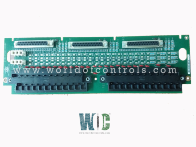
World Of Controls understands the criticality of your requirement and works towards reducing the lead time as much as possible.
IS200TBCIH1BBC - Contact Input Terminal Board is available in stock which ships the same day.
IS200TBCIH1BBC - Contact Input Terminal Board comes in UNUSED as well as REBUILT condition.
To avail our best deals for IS200TBCIH1BBC - Contact Input Terminal Board, contact us and we will get back to you within 24 hours.
Part No.: IS200TBCIH1BBC
Manufacturer: General Electric
Country of Manufacture: United States of America (USA)
Size 33.02 cm high x 10.16 cm wide (13.0 in. x 4.0 in)
Temperature Operating: -30 to 65 o C
Product Type: contact input terminal board
Availability: In Stock
Series: Mark VI
IS200TBCIH1BBC is a contact input terminal board developed by GE. It is a part of Mark VI series. Within the Mark VI system, the terminal board establishes connections to the VME rack through cables featuring molded plugs. These cables link the terminal board to either the VCCC or VCRC processor board situated within the rack. Both simplex and TMR (Triple Modular Redundant) systems are fully supported configurations for this connection.
The board is designed to accommodate 24 dry contact inputs, effectively organized and wired to two barrier type terminal blocks. Direct current (DC) power is specifically routed into the component for contact excitation purposes, ensuring optimal functionality of the contact inputs.
To safeguard against potential damage caused by surges and high-frequency noise, the contact inputs are fortified with dedicated noise suppression circuitry, enhancing their resilience and reliability in varying operational environments.
In a Mark VIe system setup, the I/O packs are connected and integrated into the TBCI. These packs are affixed to side-mounting brackets for secure installation. Depending on the system's configuration, one or two Ethernet cables may need to be plugged into the pack, potentially requiring firmware downloads to ensure proper functionality.
The WOC team is always available to help you with your Mark VI requirements. For more information, please contact WOC.
What is IS200TBCIH1BBC?
It is a contact input terminal board developed by GE under the Mark VI series.
What happens if the excitation voltage drops below a certain threshold?
If the excitation voltage decreases to less than 40 percent of the nominal voltage, the I/O pack triggers a diagnostic alarm. This alarm is set and latched, signaling a potential issue with the excitation voltage.
Is there test functionality for the inputs associated with the terminal board?
Yes, a diagnostic test can be initiated to force all inputs connected to this terminal board into the open-contact (fail-safe) state. Inputs that fail this diagnostic test are also forced into the fail-safe state, triggering a fault to indicate a potential issue.
What action is taken if the input values don't align in a TMR setup?
In a TMR (Triple Modular Redundant) configuration, if the input value from this board does not match the TMR voted value obtained from all three boards, a fault is generated, indicating a discrepancy between the input values.